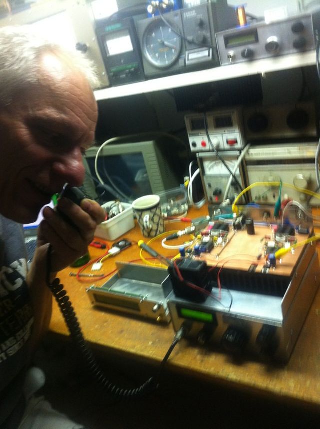
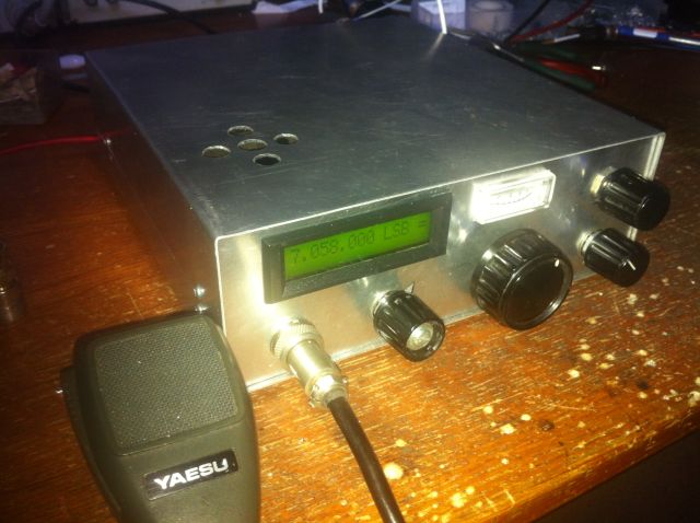
The vco of the transceiver is a DDS built with a AD9850, running on 100MHz. The output of the DDS is passed through a lowpass filter and amplified by a MAV11 to give 5mW for the rx/tx mixer, an SBL-1. The SBL-1 is used for rx and tx, and switching is done with a cmos CD4066. The IF of 9 MHz is amplified by two BFR90's and demodulated in a Plessey SL1640. For LSB and USB two sideband oscillators are built with BF199. Mode is selected switching on the required oscillator. Since the vco (DDS) is always oscillating above the RF-frequency, this is easy and directly done by the mode-switch on the front.
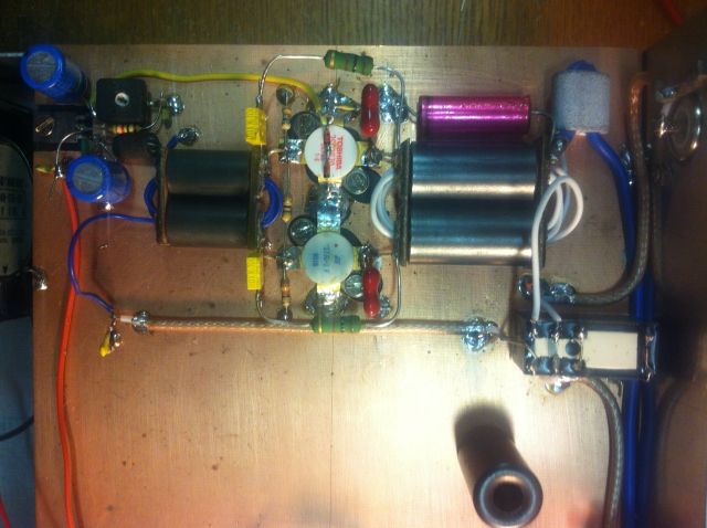
The RF from the SBL-1 is fed to a bandfilter module, made a printed circuit board. The pcb is shown here, and here the componentlayout is shown. I will update the site shortly with the schematics and a revised componentlayout where the part values are shown. Six bandfilters with Tchebichef characteristic are built on this board, and the current band is selected by switching a filter on by two small reed-relays. These are 5V types, so that the microcontroller can handle them directly. At the moment only 80, 40, 20 and 10 meter bandfilters are built on the board, so I have room for 2 other band (15 and 30 meters, but also 160 meter could be possible, or even just a lowpass filter to get a general coverage receiver if needed). The filters are built with standard coils (2.5 uH), wound on standard coilformers. The passband attenuation is 6-10dB, this is quite high and mainly depends on the losses in these coils. Some further improvements could be useful here.
The IF-strip was published in Electron, the magazine of the Dutch radio amateurs society in the 90's. The mixer is an SBL-1, and the IF side of it is switched via CD4066 CMOS-switches for TX or RX. The crystal filter is a XF9B, and the IF amplifier is build with two BFR90's. The productdetector is a SL1640 from Plessey. The audio is amplified in a 741 opamp, and used to generate the AGC and S-meter. The AGC is of the audio type, and regulating the current through two 1N4148 diode's which each short the base of the BFR90 for HF to ground via a 22nF capaitor.
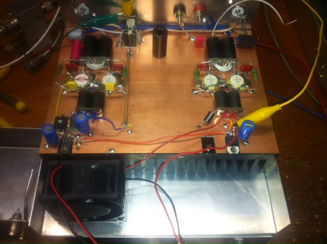
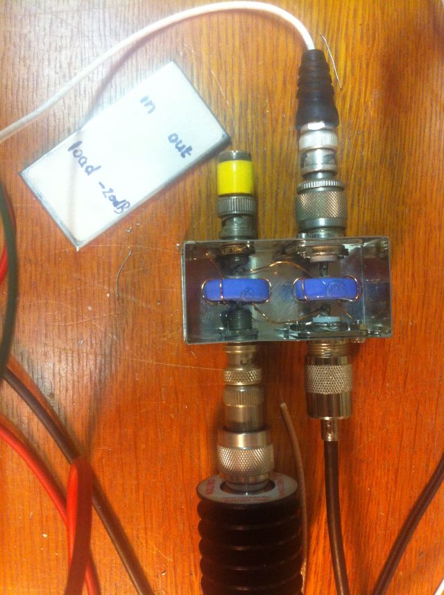
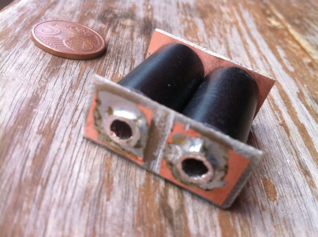
The 35W final amplifier is built with a 2SC1971 driver and 2 BLW31 power transistors. The output transformer is built with 2 ferrite pipes (www.dutchrfshop.nl) with endplates made of 2 pieces of doubleclad pcb, and with pipes made of the shield of RG214 coax. The secundary side consists of 5 turns isolated wire.
The bias of the BLW31's is built around a BD139 as emitor follower. The bias current is adjusted via a potmeter (1k) in series with 1k5 and 2 1N4148's. These diodes are thermicallu coupled with (one of the) BLW31.
|
|